Multi engine systems
BE95 /D95A Travelair

Engine
Make : Avco Lycoming
Model: IO-360 B1B
Type:
4 cylinders
Horizontally opposed
Fuel injected
Air cooled (Engine oil helps cooling)
Direct drive(Propeller is attached to the crank shaft directly without any reduction gear or transmission)
Normally aspirated(No turbo charge)
Horsepower: 180 BHP
Fuel injection
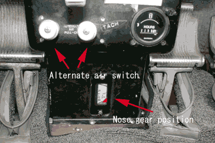
Alternate air
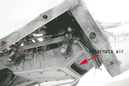
Cowl flap
Propeller
Make
Model
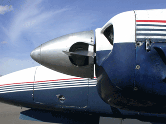
Type: Constant speed, full feathering propeller
What is a constant speed prop?
The propeller which maintains the RPM selected by propeller control lever constant regardless of airplane’s pitch attitude or throttle position within some range.
The advantage of a constant speed prop.
The pilot can select the most efficient blade angle for each phases of operation. By selecting low pitch/high RPM, you can get maximum power for takeoff. By selecting high pitch/low RPM, you can fly faster at low RPM and you can save the fuel for cruise.
How does it work?
When the airplane rise it’s nose, it start climb. As it climb, airspeed goes down. The RPM is also going down due to increasing drag on the blade. However, blade angle is decreased automatically to reduce the drag to maintain the RPM constant.
When the airplane drops it’s nose, it start to descend. As it descend, airspeed will increse. The RPM is also increased due to decreasing drag on the blade. However, blade angle is increased automatically to increase the drag to maintain the RPM constant.
Where is the governor located?
Rear side of the engine.
What does governor do?
The fly weight inside the governor senses the change in RPM by sensing the change in centrifugal force. It opens the pilot valve. When the RPM increase, the valve opens the line without the pump. It drains the oil back from propeller hub to increase the blade angle. When the RPM decrease, the valve opens the line with the pump. The pump send the oil to propeller hub to decrease the blade angle.
What makes it high pitch?
Nitrogen charged in the hub and counter weight at the root of the propeller blades.
What makes it low pitch?
High pressure of the oil and aerodynamic force on the prop.
What does pilot do when he move the prop lever in the cockpit? What will happen to governor?
It change the tension of the speeder spring. High tension requires more centrifugal force on the fly weight. It increase the RPM. Low tension requires less centrifugal force on the fly weight. It decrease the RPM.
Where is the oil from?
Engine oil reservoir at the bottom of the engine.
What will happen if you lose engine oil completely?
It become high pitch. Moves toward feathering.
How can you feather manually?
Move the propeller lever all the way down to the feather detent.
What is the purpose of feathering?
To reduce the drag caused by windmilling. To avoid further damage to the engine.
What force makes it feather?
Nitrogen charged in the hub and counter weight at the root of the propeller blades.
How can you unfeather the prop?
Move the prop lever to high RPM position to activate the unfeathering accumulator.
How does the unfeatering accumulator work?
It has diaphragm inside. Nitrogen is charged in one side. Engine oil is pumped in on the other side from the governor during normal operation. When the propeller lever is moved down to feather position, the valve is closed to keep high oil pressure inside the accumulator(300PSI). When the prop lever is moved to high RPM position, the valve is opened and the nitrogen push the oil back. The oil is sent to the hub through the governor and crankshaft to decrease blade angle. Once the blade angle changes, the wind pick up the prop to start windmill. In this way, the engine can be restarted without stress on the cylinders.
Will the prop feather when you shut down the engine after landing?
No. There is anti-feather lock pin which prevent the prop from feathering below 800 RPM. When the RPM is high, the pin hide inside sleeve due to centrifugal force. When the RPM is low, the spring push out the pin to stop the movement of the prop.
Fuel system
What is the fuel system of the Travelair?
Fuel pump system.
How many fuel pumps are there?
4. Each engine has engine driven fuel pump and electrical boost pump.
What drives fuel pumps?
Engine driven and electrical motor.
When do you use boost pump?
To start the engine as a primer. When OAT is above 95 degree F, use it for engine start, taxi, run up, takeoff, climb and landing. When the engine driven pump is inoperative.
How many fuel tanks are there?
4. Main tank and auxuary tank.
What is the capacity of each tanks( total/usable)?
25 gallons in each main tank and 31 gallons in each aux tank. Total 112 gallons.
Each main tanks have 3 gallons of unusable fuel. Total usable fuel is 106 gallons.
When can you use the aux. tank? Why?
Only in cruise. There is a baffle in the main tank which limits the movement of fuel to ensure fuel supply. But aux. tank doesn’t have the baffle. For this reason, main tank must be selected for takeoff and landing.
What is the minimum fuel requirement for takeoff?
13 gallons in each main tank.
What is the maximum duration of slip?
30 sec.
How many fuel quantity gauges are there?
2. There is the fuel gauge selector switch to show both main and aux. tank.
Can you send the fuel from right main tank to left engine? How?
Yes. Select main tank on the right fuel selector valve then select cross feed on the left fuel selector valve.
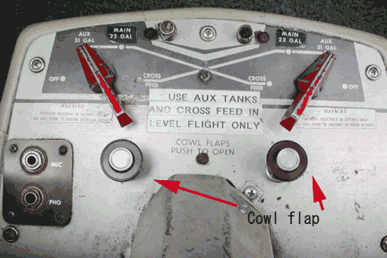
When can you use the cross feed line?
Only in cruise.
What is the purpose of cross feed?
To balance the weight laterally when one engine is inoperative. For longer range/endurance.
Draw the fuel system.
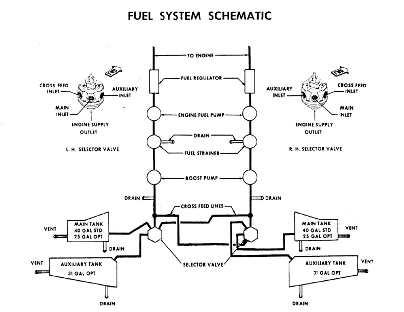
Refer P.O.H.
How many drains are there? Where are they located?
8 plus 1. Each main, each aux. tank, each fuel strainer, each cross feed line and heater.
What is the minimum grade of fuel?
100.
How can you make sure you have correct fuel?
Color. 100 is green. 100 LL is blue.
What does it mean if you see red light at the bottom of the instrument panel when you extend the gear?
Aux. tank is selected.
Landing gear
Type of the landing gear?
Tri-cycle, retractable.
How does it work?
Pilot can select the position(up/down) by the gear handle. The electrical motor rotate the gear in the gear box located below the pilot seat. Bell crank is attached to the gear which moves the push-pull rods. The other ends of the push-pull rod is attached to nose gear and each main gears.
How many motors are there?
Only one.
How can you make sure it is down and locked?
Green light(only one). When you see green light, all three gears are down and locked.
Is there anything to tell you the position of the nose gear?
There is mechanical indicator at the bottom of the main console.

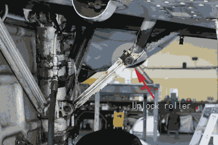
Lock systems(up/down).
Up-Up lock roller is supported by the up lock bar.
Down-Over center lock supported by push-pull rod.
What is the maximum speed you can extend/retract the gear?
165 MPH.
Is there any system which warns you when you forget to extend the gear for a landing?
There is warning horn. When the throttle is reduced(14") with gear up, it beeps. It beeps on the ground when the gear handle is up.
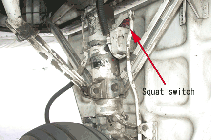
What will happen if you move gear handle up while you taxi on the ground?
The warning horn beeps. The gear will not go up because of the squat switch located on the left main gear strut.
What would you do if you don’t see green light after you move the gear handle down?
Check master switch on, circuit breaker in, push the light bulb for test, switch the light bulb, turn the bulb to the left to brighten it.
Explain the manual extension procedure.
Use check list. 1) Landing gear motor circuit breaker-pull. 2) Landing gear lever-down. 3) Hand crank counter clockwise more than 50 times. 4) Check green light. 5) Store the crank .
Can you retract the gear with manual extension system?
No. Gravity and air resistance acts against the crank. It may brake the crank.
Electrical system
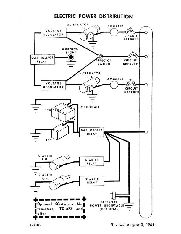
What is the primary source of electricity?
Alternator
How many alternators are there?
Two
What drives the alternator?
Engine
What is the voltage and capacity of the alternator?
24 volt, 50 Am
How can it maintain the voltage constant while the engine RPM changes from phase to phase?
Voltage regulator maintain it at 24 volt regardless of RPM.
How many voltage regulators are there? How many of them are in use?
Two. One is in use and the other is stand by. There are switch to select one of them.
What is happening if you see over voltage warning light?
Over voltage relay shut down the line as a result of over voltage caused by spike or voltage regulator failure. Recycle the master switch in the case of spike. If you still see the light on, switch the voltage regulator.
How can you make sure one of the alternators is working or not?
Turn off the alternator one at a time. If the other load increase, the alternator you turned off was working.
What is bus bar? Location? How many bus bars are there?
Bus bar is a piece of metal used for the distribution of the electricity. It simplify the wiring. It is located behind the circuit breakers. There are two bus bar s. One is main bus, the other is avionics bus.
How can you detect the alternator failure? What would you do then?
One or both load meters indicate zero. If only one indicates zero, turn off the other one to make sure it is working. If both indicate zero, check master switch on, circuit braker, switch voltage regulator. If it still indicate zero, turn off the master switch to conserve the battery.
How many batteries are there? Location?
One battery in the nose baggage compartment..
What is the voltage and capacity of the battery?
24 volt, 17 amh
How long does the battery last after losing alternator?
Depend on the load. If you use 17 am continuously, it last 1 hour. If you use 34 am continuously, it last 1/2 hour.
Flap
Type of flap: Single slotted
How does it work?
Flap is actuated by electrical motor.
Maximum deflection: 28 degreees
Vfe: 130 MPH
Vacuum system
Purpose
To operate the gyro instruments. AI and HI.
Source of vacuum
Two engine driven vacuum pumps.
Normal indication
5 in-hg±α
How to detect the failure
There are red flags on the vacuum gauge.
Heater
Ice protection
Hydraulic system
Draw the airspeed indicator.
V speed
Va
Vx
Vy
Vxse
Vyse
Vsse
Vmc
Vs0
Vs1
Vno
Vne
Vfe
Vle
Vr